Date: Thu, 18 Jun 2009 09:21:03 -0700
yes, my boat has been "molested" , esp with distributors last
summer, and has some non-stock things happening. But I think
the original distributer may have ended up back in there - I can tell
because of the blue paint on it's base. Anyway......
>
> JD:
>
> 1) What year is your boat (only applies to wiring COLOR changes)?
> What Distributor do you have? More importantly what's inside your
> distributor? (See item 3 below.)
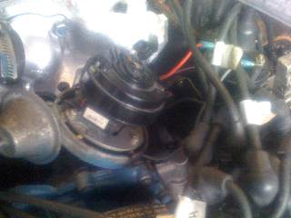
BOAT: '64 ENGINE: odd fire V-6 155 '70
DISTRIBUTOR: Couldn't see any brand but little condensor looking
thing on underside of "points" says 46AB-V4, and the side of dist
body is stamped 1110376 9010
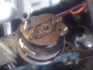
HERE'S PHOTOS (taken with phone so kinda fuzzy):
Still has points for sure, and they look pretty archaic - so maybe
this IS the original. However their enclosed in a more modern
looking black plastic housing. I know 2-3 distributors were tried
last year by mechanic/me trying to getting the engine tuned (more on
that in separate email). I'm thinking maybe it's the original
dist with some sort of aftermarket point set up. ?
1) So distributor definitely has a black AND red wire coming out the
bottom. And according to your explanation I should only have a
single black. So then is it OK that my red one goes to the (+) on
the coil? Or is it supposed to go somewhere else? Engine is
starting great, and for the most part running pretty good (more on
that in separate email)
jeff
On Jun 17, 2009, at 11:50 AM, Lee Shuster wrote:
>
> JD:
>
> 1) What year is your boat (only applies to wiring COLOR changes)?
> What Distributor do you have? More importantly what's inside your
> distributor? (See item 3 below.)
>
> 2) Coil labels: "BATT" = + (POS)(usually RED and RED/WHITE or
> PURPLE/BLACK on later OMC's)
> "DIST" = - (NEG) (usually BLACK is usally the distributor-
> points lead and GRAY is usually the TACHO lead)
>
> 3) An OEM OMC (Delco or Mallory) distributor (and most ALL other
> point-based distributors) will ground thru the distributor engine
> mounting clamp. On an stock OEM distributor (using points) the only
> wire should be the BLACK wire, which if you open up the distributor
> connects to the points and condensor. (Of course I'm ignoring the
> distribultor's SECONDARY High Tension/Voltage -- coil/spark plug
> wires).
>
> It sounds like you have an aftermarket electronic (pointless)
> upgrade internal to your stock OMC distributor. And some of these
> systems (depending on make/model) will work with stock external
> ballast resistor coils or some can run without the external ballast
> resistor and use a 3-ohm internally ballasted coil and others can
> use a special low (.5 ohm primary resistance coil). Since neither of
> us know what you REALLY have it's impossible for me to say. I can
> tell you this: No OEM OMC distributor has both red and black
> wire(s). Your extra red wire is most likely an aftermarket power
> lead for a pointless electronic ignition system. You might find
> these links helpful:
>
> http://www.pertronix.com/prod/ig/ignitor/default.aspx
> http://www.pertronix.com/catalogs/pdf/ptx/2007/ptx07_marine.pdf
> http://www.pertronix.com/catalogs/pdf/ptx/2007/ptx07_coil.pdf
>
> Using the measurements I described in my previous e-mail you can
> determine what type coil you have and if it's appropriate for use
> with your external ballast reistor and whatever electronic ignition
> system you find lurking inside your distributor. It's entirely
> possible you don't have optimally matched components.
>
> It's very simple to bypass the external ballast resistor should it
> not be needed. I'm not suggesting you do that until you figure out
> what you have. But I've done that on my own boat, which runs a
> hotter coil that doesn't require an external ballast resistor. But I
> did leave the ballast reistor in place, as it still serves as a
> convenient wiring junction point.
>
> Lee Shuster
> Utah
>
>
>
> -----Original Message-----
> From: omc-boats-bounces@... [mailto:omc-boats-bounces@...
> ] On Behalf Of jd
> Sent: Wednesday, June 17, 2009 10:29 AM
> To: Evinrude & Johnson Boats of the 1960's and 70's
> Subject: Re: [OMC-Boats] Wiring questions
>
> thanks Lee - yes, after sending that email i tested things with the
> ignition off and it all cooled down. I've been doing some other
> stuff with the temp gauge and had the ignition on for a while.
> yes, the ballast resistor gets hot. It measured 225 degrees with
> my sensor gun.
>
> I think my wiring is ok - atleast between the coil / BR / starter /
> ignition. I have a '69 wiring diagram, but it's a bit weird around
> the distributor/coil area. they don't label the coil as having (+)
> and (-) terminals, they show it as "batt" and "dist". The diagrams
> for '68 and '73 are a bit more clear with the coil. So i think
> I'm good with the coil, and the ignition being on clears up the
> heating up issue. But now I am questioning the distributer
> wiring. Now I have 3 wiring diagrams to go off and they all kinda
> show the same thing for the wires (the little ones) coming out of the
> distributer. The all show "black" going to the (-) side of the
> coil. And then they show the ground symbol coming off the bottom of
> the distributer. My distributor, which likely is not OEM, has a
> black and red wire coming off the bottom. Right now the black goes
> to - on the coil, and red to +.
>
> 1) is that right? None of the diagrams show what to do with any
> positive wire coming off the distributor - they just seem to leave
> that off. So should my red wire go to the + of the coil?
>
> 2) they specifically say black from distributor to (-) of coil, then
> go on to show a separate ground for the distributor. Or Is this
> meaning the dist grounds to the engine AND to the coil?
>
> 3)Should the grey tach wire go to the (-) or (+) of the coil. Mine
> is on the (-) of the coil, and the tach doesn't work.
>
> thanks!
>
>
>
>
> On Jun 17, 2009, at 8:15 AM, Lee Shuster wrote:
>
>> JD,
>>
>> Sometimes electrical terminology gets confused with thermodynamics
>> terminology. I'm going to assume when you use the term "HOT" you
>> mean
>> thermally, not (necessarily) presence of electrical potential
>> (voltage) although it sounds like both may possibly be present.
>>
>> Let's also clear up some other terms. An engine can be not running,
>> (as in it just stalled) while the helm-mounted IGNITION switch is
>> still in the ON position. The original OMC Ignition switch has OFF -
>> ON (RUN) - START positions.
>> Note: Unlike most automotive applications, there is no ACCESSORY
>> position on this switch. You can retrofit a new switch if you want
>> to
>> run electronics or other devices with the motor not running.
>>
>> NEVER Leave the IGNITION SWITCH in the ON position when the engine is
>> NOT running. The ballast resistor and coil will heat up under normal
>> operating conditions, but you risk damage and failure leaving the key
>> ON with the engine not running. Also with the switch ON, if your
>> sterndrive was out of water and in gear (forward or reverse)
>> additional current would flow to the clutch coils and generate excess
>> heat in the lower unit. At the very least you'll potentially drain
>> down and discharge a marginal battery and not be able to raise or
>> lower your power lift or start your engine. And we know how much
>> wives
>> or significant others love that!
>>
>> I've never taken ballast or coil temp measurements after prolonged
>> (normal) usage, but I would imagine they will be quite warm. But
>> here's what's more important: The resistor and coil WILL cool off
>> rapidly when you shut the IGN SW OFF.
>> So do that check, as well as the the other checks I've listed below.
>> There should obviously be no voltage present with the IGN SW in the
>> OFF position at the coil or ballast resistor.
>>
>> Here's a couple of factory OMC wiring diagram you can reference (both
>> wired identically, just different wiring color schemas depending on
>> age of your boat):
>>
>> http://hhscott.com/evinrude/images/wiring/68_v6_ALL_WIRE.jpg
>> http://hhscott.com/evinrude/images/wiring/73_OMC_V8_all_big.jpg
>>
>> I can't tell from you description if your boat has been re-wired or
>> mis-wired. On the POS (+) side of the coil, one (red) wire should
>> trace back to the ballast resistor and measure about 6 - 8 volts with
>> the IGN Switch ON. The other wire should be RED/WHITE STRIPE and it
>> should run back to the starter solenoid. It should measure
>> 12-13 volts only when the SWITCH is in the START position.
>>
>> This additional info may help you/others to better understand why
>> Ballast Resistors are sometimes used in Coil-Points Ignition systems.
>>
>> There are many misconceptions about ballast ignitions and what they
>> do. Up until about 1955, most vehicles used 6-volt systems. When the
>> switch was made to 12-volt system, higher compression V8 engines were
>> putting greater demands on ignition systems. Some bright engineer got
>> the idea that a hotter spark could be provided using existing 6-volt
>> coils. The full 12-volts is "temporarily" provided for "hotter"
>> staring spark, and then the coil is returned to operated on 6 to 8
>> volts during normal running. The ballast resistor is what reduces the
>> 12-14 volts essentially in half. If you know Ohms law you do the
>> math.
>>
>> The ballast ignition system includes an external resistor in series
>> with the voltage supply to the coil's (+) terminal. A internal
>> resistor coil will have an internal resistance close to 3 ohms on its
>> primary windings. The coil for a ballast ignition system (As on OEM
>> OMC boats) will have a primary winding resistance between 1 and
>> 2 ohms. The external ballast resistor will typically provide an
>> additional 1.5 - 2 ohms of resistance.
>>
>> Current flowing through the ballast resistor will create a voltage
>> drop and thus lower the coil's operating voltage to something between
>> 6- and 9-volts.
>>
>> Together, the ballast resistor and the internal resistance of the
>> coil
>> limit the current flowing through the system. The coil in a ballast
>> ignition system will have a second connection on its (+) terminal.
>> (sometimes these are joined on the ballast resistor, rather than the
>> coil) This second connection is from the starter solenoid. During
>> cranking the coil's (+) terminal will receive full battery voltage.
>> This produces a MUCH hotter spark to help the engine start. Once the
>> starter is released the coil receives its power through the external
>> resistor which drops its operating voltage to the 6 - 9 v range.
>>
>> The ballast coil can thus produce a hotter spark for starting.
>> However, if the ballast coil is wired into the ignition system
>> WITHOUT
>> the external resistor it will always operate at high voltage. The
>> increased current flow through the system and the higher spark
>> voltages will cause premature failure of the distributor points. It
>> is
>> imperative therefore that the proper coil be installed to maximize
>> its
>> ignition system reliability and life.
>> When troubleshooting a ballasted ignition system the external
>> resistor
>> and its associated wiring must be added to the components to examine.
>>
>> It is important when buying a replacement coil that the correct type
>> is selected for the ignition system to achieve acceptable life and
>> performance. Old boat ignition systems are often modified over the
>> years and determining what is required may not be as simple as
>> referring to the owner's or service manual. Visual checks should be
>> performed first. Externally ballasted ignitions use a ballast
>> resistor between the ignition switch and the coil (+) terminal
>> (frequently RED or sometime PURPLE/BALCK in color). The ballast
>> resistor will typically appear as a small ceramic brick (with wires)
>> mounted in the vicinity of the coil itself and connected between the
>> ignition switch and coil (+). Ballast ignition systems also have a
>> wire between the coil (+) terminal and the starter solenoid.
>>
>> If the boat's electrical system is totally unmolested these visual
>> clues may be enough to identify the ignition coil type installed/
>> needed.
>>
>> To confirm the needed coil type it is best to make electrical
>> measurements with a volt/ohm meter. Start by measuring the resistance
>> across the coil's low-tension terminals with all the wires
>> disconnected. Note this resistance value but do presume it correctly
>> identifies the coil needed. Perform the following additional test:
>> Re-attach the low-tension wires removed to perform the previous test.
>> Connect the volt meter between the coil's (+) terminal and chassis
>> ground. Temporarily fit a jumper wire between coil (-) and ground.
>> The
>> jumper wire will insure that current is flowing through the coil and
>> any ballast components during the test.
>> It is necessary for current to be flowing to correctly measure the
>> coil's operating voltage. With the meter and jumper wire connected,
>> switch on the ignition and observe the meter. If the meter shows
>> battery voltage (nominally 12V), the system is non-ballasted and
>> needs
>> a standard (internally ballasted) ignition coil. If the meter
>> displays
>> anything between 6V and 9V, a ballast-type ignition coil is required
>> regardless of what type of coil is currently on the boat.
>> Internally ballasted ignition coils will have a primary resistance
>> close to 3 ohms, while externally ballasted ignition coils are
>> typically between 1 ohms and 2 ohms. Using a standard (internally
>> ballasted) coil on an externally ballasted ignition system will
>> result
>> in low spark voltages potentially leading to running problems.
>> Using a
>> ballast-type coil on a standard ignition system (without an external
>> ballast resistor) will result in excessive current flowing through
>> the
>> ignition system. This will cause premature wear of the points and
>> potentially lead to reduced coil life.
>>
>> Lee Shuster
>> Utah
>>
>>
>> On Jun 16, 2009, at 8:47 PM, jd wrote:
>>
>>> Two different mechanix have messed with my wiring and even though it
>>> started/ran yesterday, things don't seem right....
>>>
>>> 1) what is the ballast resistor for and is it supposed to be 200+
>>> degrees when engine is off/cold? I'm guessing no. Both terminals
>>> light up my tester when grounded.
>>>
>>> 2)is coil supposed to be hot when engine Is off/cold?
>>>
>>> 3) neg terminal of coil has black from distributor, and grey from
>>> tach. Pos terminal of coil has red from distributor and red coming
>>> from one of ballast resistor's terminals.
>>>
>>> Other ballast resistor has purple coming from looks like ignition.
>>>
>>> Thanks!
>>>
>>>
>>>
>>> _______________________________________________
>>> OMC-Boats mailing list
>>> OMC-Boats@...
>>> http://lists.ultimate.com/mailman/listinfo/omc-boats
>>
>> _______________________________________________
>> OMC-Boats mailing list
>> OMC-Boats@...
>> http://lists.ultimate.com/mailman/listinfo/omc-boats
>
> _______________________________________________
> OMC-Boats mailing list
> OMC-Boats@...
> http://lists.ultimate.com/mailman/listinfo/omc-boats
> _______________________________________________
> OMC-Boats mailing list
> OMC-Boats@...
> http://lists.ultimate.com/mailman/listinfo/omc-boats