Date: Tue, 14 Jun 2005 20:30:19 -0600
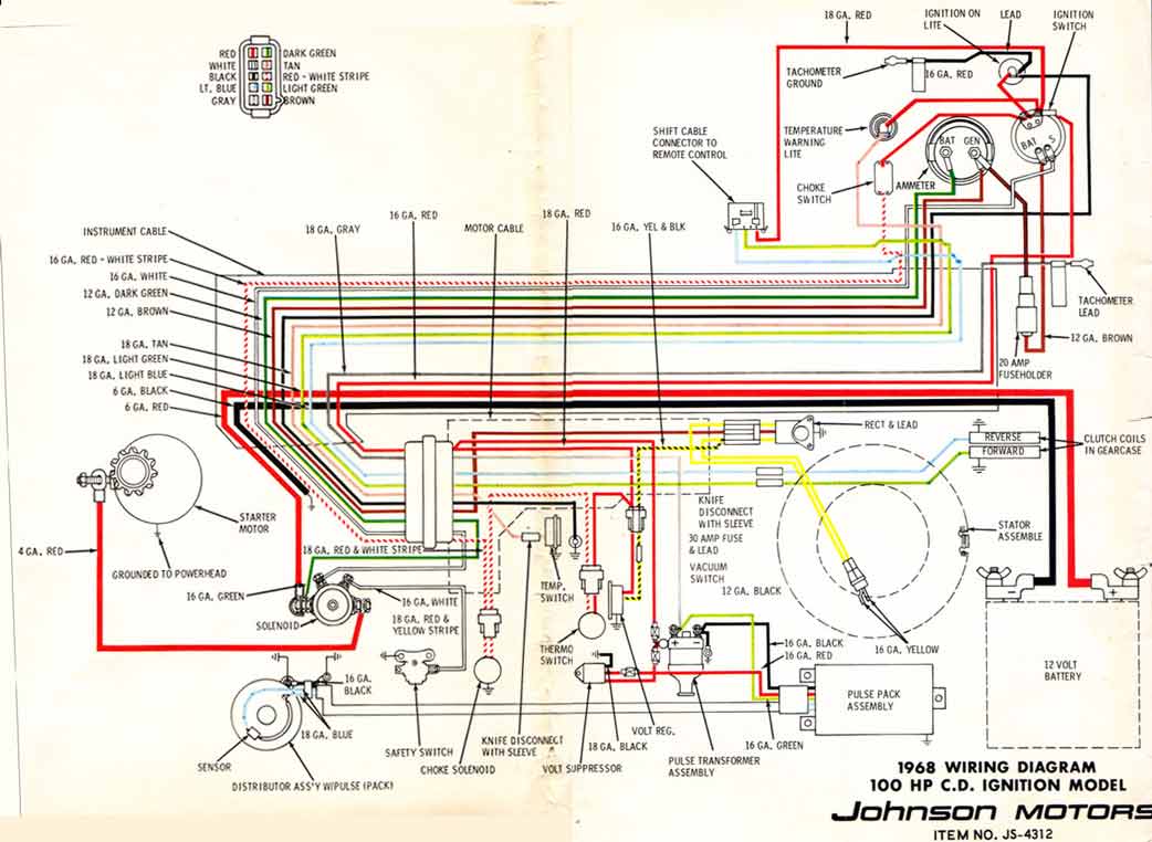
Big wires have little (gauge) numbers. For example, the smallest wire
typically used in our boats is an 18 ga, while the largest might be a 2.
See atch OMC V-4 100hp schematic.
----- Original Message -----
From: "Thomas Klauber" <tklauber@...>
To: <omc-boats-digest@...>
Sent: Tuesday, June 14, 2005 8:14 PM
Subject: [omc-boats] Re: omc-boats-digest V1 #317
>I don't know much about outboards but figure it must be easier than
>inboards. Big wires carry full power like battery and ground. I would be
>guessing the rest. You need a schematic and your best bet is ebay for
>appropriate literature for your motor. Be real careful so as not to burn up
>or short out components - they are hard to find and expensive. Best of
>luck, Tom
> ----- Original Message -----
> From: "omc-boats-digest" <owner-omc-boats-digest@...>
> To: <omc-boats-digest@...>
> Sent: Tuesday, June 14, 2005 12:00 PM
> Subject: omc-boats-digest V1 #317
>
>
>>
>> omc-boats-digest Tuesday, June 14 2005 Volume 01 : Number
>> 317
>>
>>
>>
>> [omc-boats] Nice Rogue
>> RE: [omc-boats] Wiring Sub Harnesses
>>
>> ----------------------------------------------------------------------
>>
>> Date: Mon, 13 Jun 2005 15:56:09 -0500
>> From: "Glenn Halweg" <glennhalweg@...>
>> Subject: [omc-boats] Nice Rogue
>>
>> This is a multi-part message in MIME format.
>>
>> - ------=_NextPart_000_002E_01C57030.6A331180
>> Content-Type: text/plain;
>> charset="iso-8859-1"
>> Content-Transfer-Encoding: quoted-printable
>>
>> http://tinyurl.com/daj7j
>> - ------=_NextPart_000_002E_01C57030.6A331180
>> Content-Type: text/html;
>> charset="iso-8859-1"
>> Content-Transfer-Encoding: quoted-printable
>>
>> <!DOCTYPE HTML PUBLIC "-//W3C//DTD HTML 4.0 Transitional//EN">
>> <HTML><HEAD>
>> <META http-equiv=3DContent-Type content=3D"text/html; =
>> charset=3Diso-8859-1">
>> <META content=3D"MSHTML 6.00.2900.2627" name=3DGENERATOR>
>> <STYLE></STYLE>
>> </HEAD>
>> <BODY bgColor=3D#ffffff>
>> <DIV><FONT face=3DArial=20
>> size=3D2><STRONG>http://tinyurl.com/daj7j</STRONG></FONT></DIV></BODY></H=
>> TML>
>>
>> - ------=_NextPart_000_002E_01C57030.6A331180--
>>
>> - -----
>> To get off this list send mail to omc-boats-unsubscribe@...
>>
>> ------------------------------
>>
>> Date: Tue, 14 Jun 2005 11:38:34 -0400
>> From: Ian Torrey <itorrey@...>
>> Subject: RE: [omc-boats] Wiring Sub Harnesses
>>
>> This message is in MIME format. Since your mail reader does not
>> understand
>> this format, some or all of this message may not be legible.
>>
>> - ------_=_NextPart_001_01C570F6.16FE6084
>> Content-Type: text/plain;
>> charset="iso-8859-1"
>>
>> Hi folks. I have a more basic wiring question I was wondering if someone
>> could help with. My Sweet 16 with vintage 100hp Johnson outboard has more
>> cables and wires than I know what to do with at the battery terminals,
>> and
>> no clear indication of what attaches where. So far I've never managed to
>> get
>> this to turn over since I bought it (I admit that I haven't found a lot
>> of
>> time for actually experimenting). I presume some of the wires might be
>> for
>> aftermarket accessories, and would like to just find out what the basic
>> connections should be just to get the boat running. Anyone know of where
>> I
>> might get instructions for the basic hookup?
>>
>> Thanks for all the great posts. I don't say much, but read most of them
>> :)
>>
>> Thanks,
>> Ian Torrey
>> Ottawa, ON
>>
>> - -----Original Message-----
>> From: owner-omc-boats@...
>> [mailto:owner-omc-boats@...]On
>> Behalf Of LShuster (lib1)
>> Sent: Wednesday, June 08, 2005 2:32 PM
>> To: omc-boats@...
>> Subject: Re: [omc-boats] Wiring Sub Harnesses
>>
>>
>> If wiring seems complicated, it sometimes helps to break it down, and to
>> try
>> & understand what the basic sub-harness functions are. This wiring
>> schema-design philosophy is fairly common across the entire range of
>> OMC-powered 4-stroke I/O boats. There are some minor differences between
>> years and models but they are relatively minor. The 2-stroke V-4's are
>> quite
>> different on the motors themselves and use a slightly different
>> motor-to-dash cable assembly from their more common 4-stroke brothers.
>> For
>> easier service, that dash/switch panels were modularly connected in later
>> models (pos-'67). 1) Battery Cable Assembly (easiest of all to reproduce)
>> Red (+) runs from battery to Starter solenoid, Black (-) to engine ground
>> 2) Terminal block (usually 4-post) located in engine area, sometimes
>> there
>> may also be one under the dash.
>> 3) Fuse Block (located under dash) usually has both pos and neg feed
>> inputs
>> with 9 fused outputs and ground buss terminals. Uses common "glass-type"
>> AGC
>> fuses. Fuse/circuit positions are lableled: Spare, Pump, Horn, Cig(ar),
>> WW,
>> Inst(rument)., Runn(ing), Int(erior) , Spare.
>> 4) Dash Panel Cable Assembly. This cable connects to your instruments,
>> warning lights, and switch gear or one end. The other end has two large
>> multiple-pin connectors that hook up to the motor-to-dash cable.
>> 5) Motor-to-Dash Cable Assembly Bow-end connects directly to the
>> ammeter,
>> while another connector hooks up to electric shift control, two large
>> connectors hook up to dash panel connectors. Note: on electric stringers
>> there is no default, "fail-safe" gear engagement system. Make sure your
>> shifter switch and wiring are working properly. Loss of power to either
>> forward or reverse coils could ruin your day. On the stern-end there are
>> two, large connectors: 1) hooks up to engine functions, and 2) connects
>> to
>> the tilt solenoids and bilge pump/blower. There's typically a stern light
>> connector and then some heavy, 8 ga wires connect the ammeter to the
>> terminal block (# above).
>> 6) Tilt/Bilge/Shift Harness/Cable plugs into one of the large connectors
>> from the motor-to-dash harness. Other ends run to the tilt Up and tilt
>> Down
>> solenoids, the tilt motor connector, the shifter control harness and the
>> bilge pump/blower connector.
>> 7) Engine Harness/Cable this also plugs into it's own large connector
>> from
>> the motor-dash harness. The engine items it is wired to include:
>> Alternator,
>> regulator, coil, ballast resistor, water temp sensor, oil press sensor,
>> starter solenoid and starter motor. Don't overlook the separate 8-10 ga
>> black wire running from engine ground back down to the terminal block
>> running. It's interesting that that last two cable (#6 and #7) are
>> considered part of the engine and are not listed in my Sportsman boat
>> parts
>> book. That probably means that you could pull either of those assembly
>> from
>> just about any 64 - 77 electric stringer 4-stroke OMC and might
>> plug-and-play. Chances are it won't be in any better shape than the one
>> in
>> your boat now, however.
>>
>> Hope this is helpful. If your want further clarification, take a look at
>> the
>> wiring diagram(s) that Phil posted and this will make a little more
>> sense.
>> Sorry my scanner can't do it in one big continous pass.
>>
>>
>> Lee Shuster
>> Salt Lake City
>>
>>
>> - ----- Original Message -----
>>
>> From: lib1@... <mailto:lib1@...>
>> To: omc-boats@... <mailto:omc-boats@...>
>> Sent: Wednesday, June 08, 2005 8:17 AM
>> Subject: Re: [omc-boats] Wiring
>>
>> Not only can electrical problems be an annoyance (mostly) they can leave
>> you stranded, or worse, sometimes lead to fires, so this a good topic for
>> discussion.
>>
>> Tom's and Lee's different approaches to fixing wiring harnesses both have
>> their places. I've done it both ways on a number of cars and boats. Tom's
>> approach is more time consuming but is ultimately better beacuse with
>> Lee's
>> approach there's more points of potential failure introduced in the
>> electrical continuity path. But Lee's approach is more commonly performed
>> by
>> individuals and shops and can focus on an immediate problem area,
>> typically
>> with the wiring remaining in the vehicle.
>>
>> Getting, understanding and verifying the wiring diagrams is essential.
>> Sometimes on 40-year old technology someone has previously modified a
>> circuit or used a different color wire. While heat is not the enemy (as
>> it
>> is in underhood autos) corrison and moisture can and do take a toll on
>> boats. OMC used to make a tube of electrical connector "grease" that kept
>> mositure out of the connector and reduced the chance of oxidation or
>> corrosion. You don't need the OMC stuff, auto parts and electrical supply
>> places carry it under different names.
>>
>> One thing I have learned, it's always best to pull the harness completely
>> out of a vehicle and then lay it out and tag the connectors. This makes
>> it
>> much easier to measure lengths and to access, inspect and replace
>> connectors
>> and pins. Take pictures of the connections and make notes before removal
>> if
>> your unsure of how it all connects. I find I can take my time and do a
>> much
>> better job on the workbench, rather than curled up under the dash or
>> reaching under or across a motor.
>>
>> The process that Tom K. describes can be done at home, but I would add
>> another tip: Start by practicing on a small sub-section, perhaps
>> involving
>> something non-critical like nav lights; rather than the tilt or bilge
>> blower/pump. Also, for anyone that's afraid to do this yourself, I know
>> of a
>> professional shop (they normally manufacture airbag harnesses) that will
>> make a completely new vehicle harness, using your old harness as a
>> pattern.
>> But be prepared to fork over big money to have someone else to it
>> right --
>> on the order of $900 to $1200 for parts & labor for a complete wiring
>> makeover.
>>
>>
>> Lee Shuster
>> Salt Lake City
>>
>> - ----- Original Message -----
>> From: Thomas Klauber <mailto:tklauber@...>
>> To: omc-boats-digest@... <mailto:omc-boats-digest@...>
>> Sent: Tuesday, June 07, 2005 7:30 PM
>> Subject: [omc-boats] Wiring
>>
>> This message is to all but especially Jay. Here is the way to redo the
>> wiring harness - it is not the cheapest but is a total redo. First get a
>> Clymer and a Seloc manual which you really should have already. Find a
>> used
>> OMC Stern Drive Service Manual for your year and horsepower boat on ebay
>> (
>> easier said than done but patience will pay off ). You will find wiring
>> diagrams in all 3 of these publications and each will show the wiring in
>> a
>> slightly different format but with enough study you can confingure what
>> is
>> supposed to be on your particular boat. The OMC edition shows the wiring
>> in
>> color. I have looked forever for used and or new wiring harnesses for the
>> older boats on ebay and they just dont exist and I did find one used one
>> that I bought and it was in pretty bad shape but I was able to use the
>> voltage regulator which you can get aftermarket anyway. Use your old
>> harness
>> for a template too. Mine was totally toasted. You cut the wires off a
>> little
>> above the entrance to the plug. There are 2 sizes of pins in the plug.
>> You
>> work each wire with its pin out the back of the plug through the smaller
>> hole. The pin is soldered and pressed on the wire end so you will have to
>> cut off the pressed part - it is impossible really to undo the pressed
>> part.
>> You do not want to damage the pin cause you are going to re-use it. If
>> the
>> pin is corroded (like 2 of mine were) then you will have to improvise a
>> new
>> pin. Dave Losvar at SeaWay Marine in Seattle has the terminals for the
>> other
>> ends of the wires if you want to get original. He even has the flag
>> terminals for the temp and oil senders ( for the idiot lights ). He has
>> the
>> knife terminal disconnects too, otherwise improvise. MAKE SURE YOU USE
>> MARINE GRADE WIRE AND TERMINALS. You buy Marine Primary Wire from West
>> Marine which sells the proper grade and color wire to rebuild properly
>> and
>> they sell it in smaller than 100 ft. spools so you dont have so much left
>> over. I would not recommend using all one color and grade (unless you are
>> selling the boat). Remember every connection you put in the harness is a
>> potential Sunday afternoon breakdown. You will end up buying 10 or so
>> small
>> spools of wire all different sizes and colors depending on the infomation
>> you gather from the manual. You get a nice wire stripper and solder the
>> wire
>> into the pin through the open end which you may have to drill to get
>> inside,
>> youll see what I mean when you get the pin out and the wire off - the
>> pins
>> are hollow. You basically are reattaching the new wire to the old pin and
>> you slide the pin and wire back into the plug. It is not easy to slide
>> the
>> wire back through the holes left in the rubber plug but if you use the
>> same
>> size wire as original it will all fit back in place totally like new. I
>> used
>> a small wire to go through the hole and pulled the wire and plug in from
>> the
>> front of the plug using a little lubricant. Position the pin back into
>> the
>> plug the same depth as original. Do this for each wire. When they are all
>> in
>> then put a little black silicone sealer in the plug end to sort of set
>> the
>> wires. They can be pulled out again but take a lot of effort and the plug
>> clamps together and they cummulatively will withstand a lot of pull. You
>> wrap the harness in harness tape like the original and reinstall. You
>> will
>> need to measure each wire length carefully so the fit will be proper.
>> Save
>> stuff like rubber boots and use them again. This is the basics of what I
>> did
>> and it works well ( so far ). Take your time and measure and remeasure
>> and
>> check for electrical continuity often. When you are finished you will
>> know
>> that harness like the back of your hand. It takes a long time but is
>> worth
>> it. Do it this winter. Take the warness off when you put the boat up and
>> get
>> to work.Take lots of notes. A temporary fix is to put liquid electrical
>> tape
>> on the wires to stabilize and insulate them. Once the insulation falls
>> off
>> they will corrode and fall apart. West Marine also sells Liquid Elec.
>> Tape.
>> Good luck - hope this helps. TK
>>
>>
>> - ------_=_NextPart_001_01C570F6.16FE6084
>> Content-Type: text/html;
>> charset="iso-8859-1"
>>
>> <!DOCTYPE HTML PUBLIC "-//W3C//DTD HTML 4.0 Transitional//EN">
>> <HTML><HEAD>
>> <META HTTP-EQUIV="Content-Type" CONTENT="text/html; charset=iso-8859-1">
>>
>>
>> <META content="MSHTML 6.00.2800.1498" name=GENERATOR>
>> <STYLE></STYLE>
>> </HEAD>
>> <BODY bgColor=#ffffff>
>> <DIV><SPAN class=927333515-14062005><FONT face=Arial color=#0000ff
>> size=2>Hi
>> folks. I have a more basic wiring question I was wondering if someone
>> could help
>> with. My Sweet 16 with vintage 100hp Johnson outboard has more cables and
>> wires
>> than I know what to do with at the battery terminals, and no clear
>> indication of
>> what attaches where. So far I've never managed to get this to turn over
>> since I
>> bought it (I admit that I haven't found a lot of time for actually
>> experimenting). I presume some of the wires might be for aftermarket
>> accessories, and would like to just find out what the basic connections
>> should
>> be just to get the boat running. Anyone know of where I might get
>> instructions
>> for the basic hookup?</FONT></SPAN></DIV>
>> <DIV><SPAN class=927333515-14062005><FONT face=Arial color=#0000ff
>> size=2></FONT></SPAN> </DIV>
>> <DIV><SPAN class=927333515-14062005><FONT face=Arial color=#0000ff
>> size=2>Thanks
>> for all the great posts. I don't say much, but read most of them
>> :)</FONT></SPAN></DIV>
>> <DIV><SPAN class=927333515-14062005><FONT face=Arial color=#0000ff
>> size=2></FONT></SPAN> </DIV>
>> <DIV><SPAN class=927333515-14062005><FONT face=Arial color=#0000ff
>> size=2>Thanks,</FONT></SPAN></DIV>
>> <DIV><SPAN class=927333515-14062005><FONT face=Arial color=#0000ff
>> size=2>Ian
>> Torrey</FONT></SPAN></DIV>
>> <DIV><SPAN class=927333515-14062005><FONT face=Arial color=#0000ff
>> size=2>Ottawa, ON</FONT></SPAN></DIV>
>> <BLOCKQUOTE dir=ltr style="MARGIN-RIGHT: 0px">
>> <DIV class=OutlookMessageHeader dir=ltr align=left><FONT face=Tahoma
>> size=2>-----Original Message-----<BR><B>From:</B>
>> owner-omc-boats@...
>> [mailto:owner-omc-boats@...]<B>On Behalf Of </B>LShuster
>> (lib1)<BR><B>Sent:</B> Wednesday, June 08, 2005 2:32 PM<BR><B>To:</B>
>> omc-boats@...<BR><B>Subject:</B> Re: [omc-boats] Wiring Sub
>> Harnesses<BR><BR></FONT></DIV>
>> <DIV><FONT face=Arial size=2>If wiring seems complicated, it sometimes
>> helps
>> to break it down, and to try & understand what the basic
>> sub-harness
>> functions are. This wiring schema-design philosophy is fairly
>> common
>> across the entire range of OMC-powered 4-stroke I/O boats. There
>> are some
>> minor differences between years and models but they are relatively
>> minor. The
>> 2-stroke V-4's are quite different on the motors themselves and use a
>> slightly
>> different motor-to-dash cable assembly from their more common 4-stroke
>> brothers. For easier service, that dash/switch panels were modularly
>> connected
>> in later models (pos-'67). </FONT><FONT face=Arial size=2>1)
>> <STRONG>Battery
>> Cable Assembly</STRONG> (easiest of all to reproduce) Red (+) runs from
>> battery to Starter solenoid, Black (-) to engine ground</FONT></DIV>
>> <DIV><FONT face=Arial size=2>2) <STRONG>Terminal block</STRONG> (usually
>> 4-post) located in engine area, sometimes there may also be one under
>> the
>> dash.</FONT></DIV>
>> <DIV><FONT face=Arial size=2>3) <STRONG>Fuse Block</STRONG> (located
>> under
>> dash) usually has both pos and neg feed inputs with 9 fused
>> outputs and
>> ground buss terminals. Uses common "glass-type" AGC fuses. Fuse/circuit
>> positions are lableled: Spare, Pump, Horn, Cig(ar), WW, Inst(rument).,
>> Runn(ing), Int(erior) , Spare.</FONT></DIV>
>> <DIV><FONT face=Arial size=2>4) <STRONG>Dash Panel Cable
>> Assembly</STRONG>.
>> This cable connects to your instruments, warning lights, and switch gear
>> or
>> one end. The other end has two large multiple-pin connectors that hook
>> up to
>> the motor-to-dash cable.</FONT></DIV>
>> <DIV><FONT face=Arial size=2>5) <STRONG>Motor-to-Dash Cable
>> Assembly</STRONG> Bow-end connects directly to the ammeter, while
>> another connector hooks up to electric shift control, two large
>> connectors
>> hook up to dash panel connectors. Note: on electric stringers there is
>> no
>> default, "fail-safe" gear engagement system. Make sure your shifter
>> switch and
>> wiring are working properly. Loss of power to either forward or reverse
>> coils
>> could ruin your day. On the stern-end there are two, large connectors:
>> 1)
>> hooks up to engine functions, and 2) connects to the tilt solenoids and
>> bilge
>> pump/blower. There's typically a stern light connector and then some
>> heavy, 8
>> ga wires connect the ammeter to the terminal block (#
>> above).</FONT></DIV>
>> <DIV><FONT face=Arial size=2>6) <STRONG>Tilt/Bilge/Shift
>> Harness/Cable
>> </STRONG>plugs into one of the large connectors from the motor-to-dash
>> harness. Other ends run to the tilt Up and tilt Down solenoids, the tilt
>> motor
>> connector, the shifter control harness and the bilge pump/blower
>> connector.</FONT></DIV>
>> <DIV><FONT face=Arial size=2>7) <STRONG>Engine
>> Harness/Cable</STRONG> this also plugs into it's own large
>> connector from the motor-dash harness. The engine items it is
>> wired to include: Alternator, regulator, coil, ballast resistor,
>> water
>> temp sensor, oil press sensor, starter solenoid and starter motor. Don't
>> overlook the separate 8-10 ga black wire running from engine ground back
>> down
>> to the terminal block running. It's interesting that that last two
>> cable
>> (#6 and #7) are considered part of the engine and are not listed in my
>> Sportsman boat parts book. That probably means that you could pull
>> either of
>> those assembly from just about any 64 - 77 electric stringer 4-stroke
>> OMC and
>> might plug-and-play. Chances are it won't be in any better shape than
>> the one
>> in your boat now, however.</FONT></DIV>
>> <DIV><FONT face=Arial size=2></FONT> </DIV>
>> <DIV><FONT face=Arial size=2>Hope this is helpful. If your want further
>> clarification, take a look at the wiring diagram(s) that Phil posted and
>> this
>> will make a little more sense. Sorry my scanner can't do it in one big
>> continous pass.
>> <DIV><FONT face=Arial size=2></FONT> </DIV></FONT></DIV>
>> <DIV><FONT face=Arial size=2></FONT> </DIV>
>> <DIV><FONT face=Arial size=2>Lee Shuster</FONT></DIV>
>> <DIV><FONT face=Arial size=2>Salt Lake City</FONT></DIV>
>> <DIV> </DIV>
>> <DIV> </DIV>
>> <DIV>----- Original Message ----- </DIV>
>> <BLOCKQUOTE dir=ltr
>> style="PADDING-RIGHT: 0px; PADDING-LEFT: 5px; MARGIN-LEFT: 5px;
>> BORDER-LEFT: #000000 2px solid; MARGIN-RIGHT: 0px">
>> <DIV
>> style="BACKGROUND: #e4e4e4; FONT: 10pt arial; font-color:
>> black"><B>From:</B>
>> <A title=lib1@...
>> href="mailto:lib1@...">lib1@...</A> </DIV>
>> <DIV style="FONT: 10pt arial"><B>To:</B> <A
>> title=omc-boats@...
>> href="mailto:omc-boats@...">omc-boats@...</A> </DIV>
>> <DIV style="FONT: 10pt arial"><B>Sent:</B> Wednesday, June 08, 2005
>> 8:17
>> AM</DIV>
>> <DIV style="FONT: 10pt arial"><B>Subject:</B> Re: [omc-boats]
>> Wiring</DIV>
>> <DIV><BR></DIV>
>> <DIV><FONT face=Arial size=2> Not only can electrical problems be
>> an
>> annoyance (mostly) they can leave you stranded, or worse, sometimes
>> lead to
>> fires, so this a good topic for discussion.</FONT></DIV>
>> <DIV><FONT face=Arial size=2></FONT> </DIV>
>> <DIV><FONT face=Arial size=2>Tom's and Lee's different approaches to
>> fixing
>> wiring harnesses both have their places. I've done it both ways on a
>> number
>> of cars and boats. Tom's approach is more time consuming but is
>> ultimately
>> better beacuse with Lee's approach there's more points of
>> potential
>> failure introduced in the electrical continuity path. But Lee's
>> approach is
>> more commonly performed by individuals and shops and can focus on an
>> immediate problem area, typically with the wiring remaining in the
>> vehicle.
>> </FONT></DIV>
>> <DIV><FONT face=Arial size=2></FONT><FONT face=Arial
>> size=2></FONT> </DIV>
>> <DIV><FONT face=Arial size=2>Getting, understanding and verifying the
>> wiring
>> diagrams is essential. Sometimes on 40-year old technology someone has
>> previously modified a circuit or used a different color wire. While
>> heat is
>> not the enemy (as it is in underhood autos) corrison and moisture can
>> and do
>> take a toll on boats. OMC used to make a tube of electrical connector
>> "grease" that kept mositure out of the connector and reduced the
>> chance of
>> oxidation or corrosion. You don't need the OMC stuff, auto parts and
>> electrical supply places carry it under different names.</FONT></DIV>
>> <DIV><FONT face=Arial size=2></FONT> </DIV>
>> <DIV><FONT face=Arial size=2>One thing I have learned, it's always
>> best to
>> pull the harness completely out of a vehicle and then lay it out and
>> tag the
>> connectors. This makes it much easier to measure lengths and to
>> access,
>> inspect and replace connectors and pins. Take pictures of the
>> connections
>> and make notes before removal if your unsure of how it all connects. I
>> find
>> I can take my time and do a much better job on the workbench, rather
>> than
>> curled up under the dash or reaching under or across a
>> motor.</FONT></DIV>
>> <DIV><FONT face=Arial size=2></FONT> </DIV>
>> <DIV><FONT face=Arial size=2>The process that Tom K. describes can be
>> done
>> at home, but I would add another tip: Start by practicing on a small
>> sub-section, perhaps involving something non-critical like nav lights;
>> rather than the tilt or bilge blower/pump. Also, for anyone that's
>> afraid to
>> do this yourself, I know of a professional shop (they normally
>> manufacture airbag harnesses) that will make a completely new
>> vehicle
>> harness, using your old harness as a pattern. But be prepared to fork
>> over
>> big money to have someone else to it right -- on the order of
>> $900 to
>> $1200 for parts & labor for a complete wiring
>> makeover.</FONT></DIV>
>> <DIV><FONT face=Arial size=2></FONT> </DIV>
>> <DIV><FONT face=Arial size=2></FONT> </DIV>
>> <DIV><FONT face=Arial size=2>Lee Shuster</FONT></DIV>
>> <DIV><FONT face=Arial size=2>Salt Lake City</FONT></DIV>
>> <BLOCKQUOTE dir=ltr
>> style="PADDING-RIGHT: 0px; PADDING-LEFT: 5px; MARGIN-LEFT: 5px;
>> BORDER-LEFT: #000000 2px solid; MARGIN-RIGHT: 0px">
>> <DIV style="FONT: 10pt arial">----- Original Message ----- </DIV>
>> <DIV
>> style="BACKGROUND: #e4e4e4; FONT: 10pt arial; font-color:
>> black"><B>From:</B>
>> <A title=tklauber@...
>> href="mailto:tklauber@...">Thomas Klauber</A> </DIV>
>> <DIV style="FONT: 10pt arial"><B>To:</B> <A
>> title=omc-boats-digest@...
>>
>> href="mailto:omc-boats-digest@...">omc-boats-digest@...</A>
>> </DIV>
>> <DIV style="FONT: 10pt arial"><B>Sent:</B> Tuesday, June 07, 2005
>> 7:30
>> PM</DIV>
>> <DIV style="FONT: 10pt arial"><B>Subject:</B> [omc-boats]
>> Wiring</DIV>
>> <DIV><BR></DIV>
>> <DIV><FONT face=Arial size=2> This message is to all but
>> especially
>> Jay. Here is the way to redo the wiring harness - it is not the
>> cheapest
>> but is a total redo. First get a Clymer and a Seloc manual which you
>> really should have already. Find a used OMC Stern
>> Drive Service Manual for your year and horsepower boat on
>> ebay (
>> easier said than done but patience will pay off ). You will find
>> wiring
>> diagrams in all 3 of these publications and each will show the
>> wiring in a
>> slightly different format but with enough study you can confingure
>> what is
>> supposed to be on your particular boat. The OMC edition shows the
>> wiring
>> in color. I have looked forever for used and or new wiring harnesses
>> for
>> the older boats on ebay and they just dont exist and I did find one
>> used
>> one that I bought and it was in pretty bad shape but I was able to
>> use the
>> voltage regulator which you can get aftermarket anyway. Use your old
>> harness for a template too. Mine was totally toasted. You cut the
>> wires
>> off a little above the entrance to the plug. There are 2
>> sizes
>> of pins in the plug. You work each wire with its pin out the back of
>> the
>> plug through the smaller hole. The pin is soldered and pressed on
>> the wire
>> end so you will have to cut off the pressed part - it is impossible
>> really
>> to undo the pressed part. You do not want to damage the pin cause
>> you are
>> going to re-use it. If the pin is corroded (like 2 of mine were)
>> then you
>> will have to improvise a new pin. Dave Losvar at SeaWay Marine in
>> Seattle
>> has the terminals for the other ends of the wires if you want to get
>> original. He even has the flag terminals for the temp and oil
>> senders (
>> for the idiot lights ). He has the knife terminal disconnects too,
>> otherwise improvise. MAKE SURE YOU USE MARINE GRADE WIRE AND
>> TERMINALS.
>> You buy Marine Primary Wire from West Marine which sells the proper
>> grade
>> and color wire to rebuild properly and they sell it in smaller than
>> 100
>> ft. spools so you dont have so much left over. I would not recommend
>> using
>> all one color and grade (unless you are selling the boat).
>> Remember
>> every connection you put in the harness is a potential Sunday
>> afternoon
>> breakdown. You will end up buying 10 or so small spools of wire all
>> different sizes and colors depending on the infomation you gather
>> from the
>> manual. You get a nice wire stripper and solder the wire into the
>> pin
>> through the open end which you may have to drill to get inside,
>> youll
>> see what I mean when you get the pin out and the wire off - the
>> pins
>> are hollow. You basically are reattaching the new wire to the old
>> pin and
>> you slide the pin and wire back into the plug. It is not easy to
>> slide the
>> wire back through the holes left in the rubber plug but if you use
>> the
>> same size wire as original it will all fit back in place totally
>> like new.
>> I used a small wire to go through the hole and pulled the wire
>> and
>> plug in from the front of the plug using a little lubricant.
>> Position the
>> pin back into the plug the same depth as original. Do this for each
>> wire.
>> When they are all in then put a little black silicone sealer in the
>> plug
>> end to sort of set the wires. They can be pulled out again but take
>> a lot
>> of effort and the plug clamps together and they cummulatively will
>> withstand a lot of pull. You wrap the harness in harness tape like
>> the
>> original and reinstall. You will need to measure each wire length
>> carefully so the fit will be proper. Save stuff like rubber boots
>> and use
>> them again. This is the basics of what I did and it works well ( so
>> far ).
>> Take your time and measure and remeasure and check for electrical
>> continuity often. When you are finished you will know that harness
>> like
>> the back of your hand. It takes a long time but is worth it. Do it
>> this
>> winter. Take the warness off when you put the boat up and get to
>> work.Take
>> lots of notes. A temporary fix is to put liquid electrical tape
>> on
>> the wires to stabilize and insulate them. Once the insulation falls
>> off
>> they will corrode and fall apart. West Marine also sells Liquid
>> Elec.
>> Tape. Good luck - hope this helps.
>> TK</FONT></DIV></BLOCKQUOTE></BLOCKQUOTE></BLOCKQUOTE></BODY></HTML>
>>
>> - ------_=_NextPart_001_01C570F6.16FE6084--
>> - -----
>> To get off this list send mail to omc-boats-unsubscribe@...
>>
>> ------------------------------
>>
>> End of omc-boats-digest V1 #317
>> *******************************
>>
>> -----
>> To get off this list send mail to
>> omc-boats-digest-unsubscribe@...
>
>
> -----
> To get off this list send mail to omc-boats-unsubscribe@...
>
>
-----
To get off this list send mail to omc-boats-unsubscribe@...