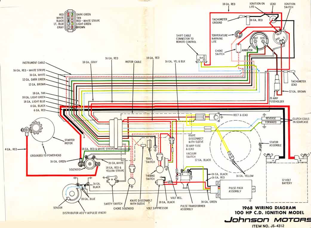
I think your 66 is a 100-S, which introduced the electronic Capacitive Discharge Ignition system (which eliminated points) on OMC outboards (also shared the big lower gear case).
Quite awhile back I posted an 1968 OMC Outboard wiring diagram at:
http://www.ultimate.com/omc-boats/gallery/lee.shuster/68_100hp_V4.jpg
which might be similar to your 66 100hp. My "guess" is you CD Ign system used an internally ballasted coil (which OMC called a "Pulse Transformer Assy.")
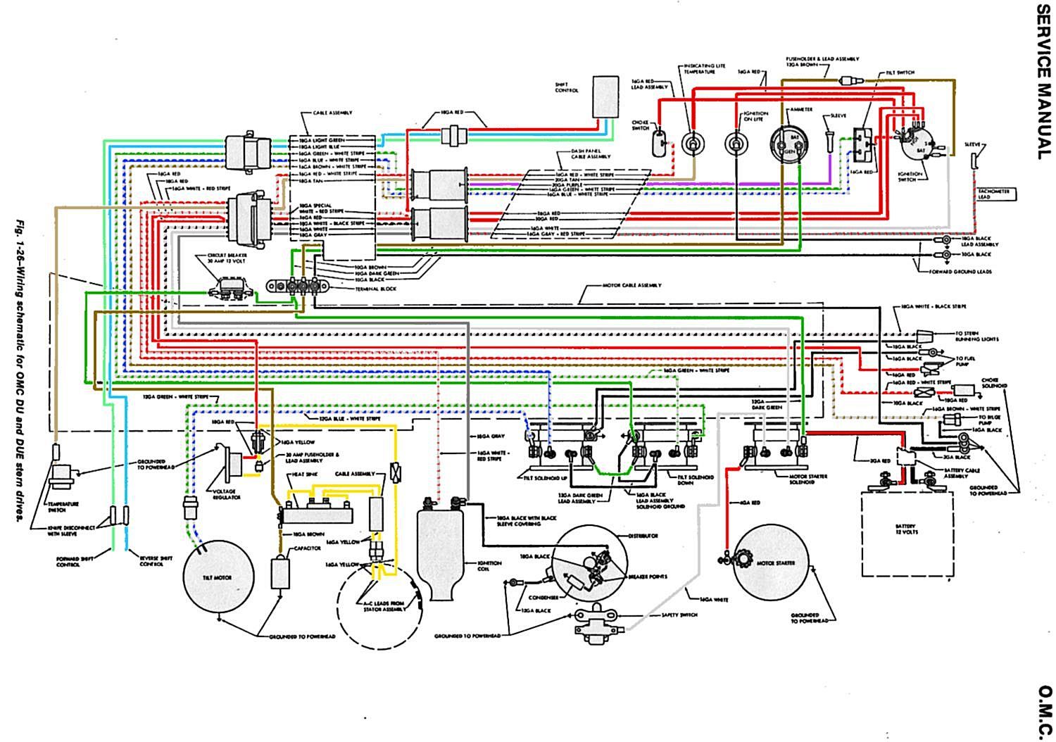
Prior to the CD IGN system, the V-4 outboards and the V-4 sterndrives all used "standard" points ignitions, shown here:
http://www.ultimate.com/omc-boats/gallery/hughes/65-68_OMC_Wiring_Schematic.jpg
Glad to help the out boarders amongst our ranks as well, but it was a l-o-n-g- winded explanation, that most people probably found boring.
Lee Shuster
Utah
________________________________
From: omc-boats-bounces@... [mailto:omc-boats-bounces@...ultimate.com] On Behalf Of Ian Torrey
Sent: Wednesday, June 17, 2009 11:00 AM
To: OMC Boats List
Subject: Re: [OMC-Boats] Wiring questions
Lee, after about 5 years of trying to figure these systems out, you've finally made this all make sense to me! Hallelujiah! Seems all of the same theory would apply to my '66 OMC 100hp motor - I could never quite figure out what the "little clay brick" was for - even with the repair manual. Thanks for taking the time to give this detailed overview.
Many thanks,
Ian
On 6/17/09 11:15 AM, "Lee Shuster" <lks@...> wrote:
JD,
Sometimes electrical terminology gets confused with thermodynamics terminology. I'm going to assume when you use the term "HOT" you mean thermally, not (necessarily) presence of electrical potential (voltage) although it sounds like both may possibly be present.
Let's also clear up some other terms. An engine can be not running, (as in it just stalled) while the helm-mounted IGNITION switch is still in the ON position. The original OMC Ignition switch has OFF - ON (RUN) - START positions.
Note: Unlike most automotive applications, there is no ACCESSORY position on this switch. You can retrofit a new switch if you want to run electronics or other devices with the motor not running.
NEVER Leave the IGNITION SWITCH in the ON position when the engine is NOT running. The ballast resistor and coil will heat up under normal operating conditions, but you risk damage and failure leaving the key ON with the engine not running. Also with the switch ON, if your sterndrive was out of water and in gear (forward or reverse) additional current would flow to the clutch coils and generate excess heat in the lower unit. At the very least you'll potentially drain down and discharge a marginal battery and not be able to raise or lower your power lift or start your engine. And we know how much wives or significant others love that!
I've never taken ballast or coil temp measurements after prolonged (normal) usage, but I would imagine they will be quite warm. But here's what's more important: The resistor and coil WILL cool off rapidly when you shut the IGN SW OFF.
So do that check, as well as the the other checks I've listed below. There should obviously be no voltage present with the IGN SW in the OFF position at the coil or ballast resistor.
Here's a couple of factory OMC wiring diagram you can reference (both wired identically, just different wiring color schemas depending on age of your boat):
http://hhscott.com/evinrude/images/wiring/68_v6_ALL_WIRE.jpg
http://hhscott.com/evinrude/images/wiring/73_OMC_V8_all_big.jpg
I can't tell from you description if your boat has been re-wired or mis-wired. On the POS (+) side of the coil, one (red) wire should trace back to the ballast resistor and measure about 6 - 8 volts with the IGN Switch ON. The other wire should be RED/WHITE STRIPE and it should run back to the starter solenoid. It should measure 12-13 volts only when the SWITCH is in the START position.
This additional info may help you/others to better understand why Ballast Resistors are sometimes used in Coil-Points Ignition systems.
There are many misconceptions about ballast ignitions and what they do. Up until about 1955, most vehicles used 6-volt systems. When the switch was made to 12-volt system, higher compression V8 engines were putting greater demands on ignition systems. Some bright engineer got the idea that a hotter spark could be provided using existing 6-volt coils. The full 12-volts is "temporarily" provided for "hotter" staring spark, and then the coil is returned to operated on 6 to 8 volts during normal running. The ballast resistor is what reduces the 12-14 volts essentially in half. If you know Ohms law you do the math.
The ballast ignition system includes an external resistor in series with the voltage supply to the coil's (+) terminal. A internal resistor coil will have an internal resistance close to 3 ohms on its primary windings. The coil for a ballast ignition system (As on OEM OMC boats) will have a primary winding resistance between 1 and 2 ohms. The external ballast resistor will typically provide an additional 1.5 - 2 ohms of resistance.
Current flowing through the ballast resistor will create a voltage drop and thus lower the coil's operating voltage to something between 6- and 9-volts.
Together, the ballast resistor and the internal resistance of the coil limit the current flowing through the system. The coil in a ballast ignition system will have a second connection on its (+) terminal. (sometimes these are joined on the ballast resistor, rather than the coil) This second connection is from the starter solenoid. During cranking the coil's (+) terminal will receive full battery voltage. This produces a MUCH hotter spark to help the engine start. Once the starter is released the coil receives its power through the external resistor which drops its operating voltage to the 6 - 9 v range.
The ballast coil can thus produce a hotter spark for starting. However, if the ballast coil is wired into the ignition system WITHOUT the external resistor it will always operate at high voltage. The increased current flow through the system and the higher spark voltages will cause premature failure of the distributor points. It is imperative therefore that the proper coil be installed to maximize its ignition system reliability and life. When troubleshooting a ballasted ignition system the external resistor and its associated wiring must be added to the components to examine.
It is important when buying a replacement coil that the correct type is selected for the ignition system to achieve acceptable life and performance. Old boat ignition systems are often modified over the years and determining what is required may not be as simple as referring to the owner's or service manual. Visual checks should be performed first. Externally ballasted ignitions use a ballast resistor between the ignition switch and the coil (+) terminal (frequently RED or sometime PURPLE/BALCK in color). The ballast resistor will typically appear as a small ceramic brick (with wires) mounted in the vicinity of the coil itself and connected between the ignition switch and coil (+). Ballast ignition systems also have a wire between the coil (+) terminal and the starter solenoid.
If the boat's electrical system is totally unmolested these visual clues may be enough to identify the ignition coil type installed/needed.
To confirm the needed coil type it is best to make electrical measurements with a volt/ohm meter. Start by measuring the resistance across the coil's low-tension terminals with all the wires disconnected. Note this resistance value but do presume it correctly identifies the coil needed. Perform the following additional test: Re-attach the low-tension wires removed to perform the previous test. Connect the volt meter between the coil's (+) terminal and chassis ground. Temporarily fit a jumper wire between coil (-) and ground. The jumper wire will insure that current is flowing through the coil and any ballast components during the test. It is necessary for current to be flowing to correctly measure the coil's operating voltage. With the meter and jumper wire connected, switch on the ignition and observe the meter. If the meter shows battery voltage (nominally 12V), the system is non-ballasted and needs a standard (internally ballasted) ignition coil. If the meter displays anything between 6V and 9V, a ballast-type ignition coil is required regardless of what type of coil is currently on the boat. Internally ballasted ignition coils will have a primary resistance close to 3 ohms, while externally ballasted ignition coils are typically between 1 ohms and 2 ohms. Using a standard (internally ballasted) coil on an externally ballasted ignition system will result in low spark voltages potentially leading to running problems. Using a ballast-type coil on a standard ignition system (without an external ballast resistor) will result in excessive current flowing through the ignition system. This will cause premature wear of the points and potentially lead to reduced coil life.
Lee Shuster
Utah
On Jun 16, 2009, at 8:47 PM, jd wrote:
Two different mechanix have messed with my wiring and even though it started/ran yesterday, things don't seem right....
1) what is the ballast resistor for and is it supposed to be 200+ degrees when engine is off/cold? I'm guessing no. Both terminals light up my tester when grounded.
2)is coil supposed to be hot when engine Is off/cold?
3) neg terminal of coil has black from distributor, and grey from tach. Pos terminal of coil has red from distributor and red coming from one of ballast resistor's terminals.
Other ballast resistor has purple coming from looks like ignition.
Thanks!
_______________________________________________
OMC-Boats mailing list
OMC-Boats@...
http://lists.ultimate.com/mailman/listinfo/omc-boats
___________________________________________________________________
Ian Torrey | Creative Director | itorrey@...
T: +1 613.271.9150 | M: +1 613.794.4596 | F: +1 613.591.3579 | http://www.qnx.com
QNX Software Systems Co., a Harman International Company |
Received on Wednesday, 17 June 2009
This archive was generated by hypermail 2.2.0 : Tuesday, 29 July 2014 EDT